
Welcome to Part 2 of the 3 part series in which I show you how I assembled a new Upper Receiver Group for my AR15. In Part 1 we looked at design considerations, legal issues, and tools. This article will cover the assembly process. Seasoned AR15 operators will know that the AR is essentially Barbie for men. AR owners can accessorize and modify their rifle with minimal training or tools. As I’m demonstrating, even the untrained can assemble the parts to build a working rifle. The AR15 is one of the few platforms where many manufacturers work within a specification and build mostly interchangeable parts.
Assembly Process
As I’ve said I am not an armorer, a gunsmith, or a professional gun fighter, and I have no training in the “correct” assembly of an AR15. However a couple of books and some research goes a long way. The web is full of resources for assembling an AR. What I’ll outline here is the process I used with the minimum of specific tools.
One item I do not have and would have greatly benefited from is a vise. I do not have space on my workbench for a vise, but will be adding one to my next workbench. Fortunately I took a correspondence course with the Wile E. Coyote School of Gunsmithing (not really, if you don’t know what you’re doing seek professional advice), which allows me to improvise a little. In this case I’ve used a set of clamps in place of a proper vise.
Ejection Port Cover
The Motiuk upper receiver came with a forward assist and ejection port cover. However I wanted to use an engraved ejection port cover. The installation could be tricky. With the ejection port cover removed;
- Insert the hinge pin until it comes to the opening in the port cover place the spring onto the hinge pin
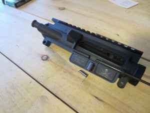
1. installing the ejection port cover
- Twist the long end of the spring 180 degrees
- The spring should have tension between the receiver and port cover
- Finish inserting the hinge pin
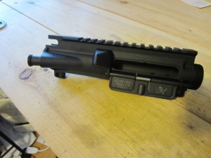
4. ejection port cover installed
To test if the cover is installed correctly, push the cover closed. Push the cover open from the inside of the receiver. The cover should snap open.
Barrel
Installing the barrel is straight forward. However, you are installing a steel barrel into an aluminum receiver, so its also very easy to damage the receiver. The barrel includes an index pin that matches with a gap in the upper receiver. Its important not to over torque the barrel or the receiver could be damaged.
This is one point in the assembly where I would have liked a vise. The poor man’s vise is pictured below. I’ve mounted the upper receiver in a receiver block and then used a bar clamp to mount the assembly securely to my work bench.
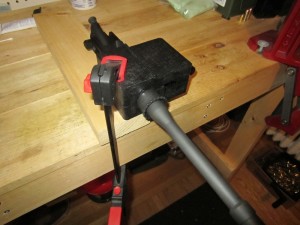
Acme gun vise
- Mount the upper receiver in a receiver block
- Lubricate the threads on the the receiver
- Install the barrel nut hand tight
- Using the armorers wrench tighten the barrel nut to between 50-70 foot pounds. The reason for the large tolerance is that you need to time a scallop in the barrel nut to align with the hole in the receiver where the gas tube will be installed. If the barrel nut is not timed correctly you will not be able to install the gas tube.
Gas System
Installing the gas block is very straight forward. There are several sizes of gas block so you need to make sure that you order the right size for your barrel. There are also several styles of gas block. I’ve selected a low profile gas block that screws into place and is made in Canada by S&J Hardware. Other styles include clamp on and pinned. I knew I was planning on using magnified optics for this rifle so a low profile gas block will be under the rail and out of my way. If I were planning to use iron sights; folding sights could be added to the rail, or the A2 style sight tower could also have been used.
The gas block is installed from the muzzle end of the barrel. The gas port on the barrel is much smaller than the gas port in the gas block, but the gas block should still be installed squarely so as not to twist the gas tube.
- Position the gas block so that the gas ports are aligned
- The S&J gas block has two set screws which are torqued using an Allen wrench
- Once the gas block is secured the gas tube can be installed by sliding it into the upper receiver and then pulling it towards the muzzle and into the gas block.
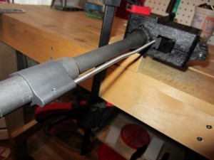
Gas block installed, with gas tube about to be pinned
With the gas block and gas tube installed, the upper receiver group can now be removed from the receiver block. The next step is the part of the build that was most difficult for me, installing the gas tube roll pin. To install the roll pin a small hammer and roll pin punch should be used. I ordered a set of roll pin punches in Part 1 to use with my nylon/brass hammer. I also ordered 3 roll pins in case I made a mistake, which I did.
- Firmly place the gas block on a secure surface
- Align the roll pin
- Gently start the roll pin using a roll pin punch and small hammer
- Continue to tap the roll pin into place.
Roll pins are press fit, and I was not able to get mine to go the last millimeter or two into the gas block. I damaged the first roll pin by hitting it too hard. The roll pin is just holding the gas tube in place and there is not much force acting on it, so not being perfectly flush with the gas block should not harm anything.
Muzzle Device
The Griffon Armament M4SDII Compensator comes packaged with a tabbed washer, a peel washer and 2″x3″ patch. The M4SDII with a a was designed to function with several models of quick detach suppressors.
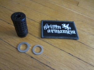
Griffin Armament M4SDII compensator package contents
The first step is separating the peel washer. The instructions say to heat the peel washer using a stove or torch. Since I have an electric stove and no torch, I resorted to a lighter. My bic lighter worked just fine to heat the peel washer, while holding it with a pair of pliers.
Using my Wile E. Coyote gun vise I mounted the barrel securely to my work bench. Using the channeled soft jars and bar clamps I fixed the barrel in place. Do not use the upper receiver vise block. The barrel extension pin is steel and the receiver is aluminum, torquing the muzzle device (and the barrel) could damage the receiver. Clamping the barrel instead of the receiver mitigates any torquing issues. Installing the muzzle device with the correct timing was tedious. The compensator is not ported on the “bottom”, but the bottom has to be aligned correctly using shims from the peel washer.
- Place a shim, from the peel washer, over the barrel threads
- Place the tabbed washer over the barrel threads
- Spin the M4SDII on hand tight
- If the “bottom” of the M4SDII is positioned around 12 o’clock proceed to step 5. If not, you need to take the comp and tabbed washer off and add another shim then repeat steps 1-4.
- Set the tabbed washer to be at 3 o’clock, especially if mounting a suppressor
- Use the armorers wrench to tighten the comp to 22 – 32 foot pounds of torque. This should put the bottom of the comp at 6 o’clock.
- If the comp is timed correctly the un-ported section of the comp will be in line with the bottom of the barrel. If not, you need to go back to step 1 and add or remove shims to adjust the timing of the comp.
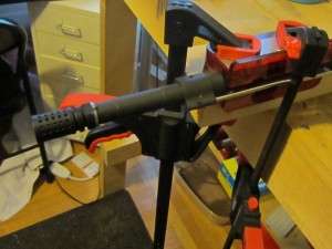
Griffin Armament M4SDII compensator installation
I had to repeat the installation process of the comp 3 times before I had the timing right.
Forend
The Samson Evolution Rail requires the stock barrel nut, which I installed when I put the barrel on the receiver. Installing the rail is very easy and is basically bolting a piece on the rifle. The rail comes with thermal bushings that ride on the barrel nut and provide an interface for the rail.
- Slip the thermal bushings on to the barrel nut. The end of each thermal bushing that has the half hole goes to the bottom of the rifle. Leave space around the gas tube between the bushings
- Make sure all of the screws on the rail are backed off, there are two on the side and a small set screw on the bottom
- Slide the rail onto the bushings
- Set the rail on the forend level with the rail on the upper receiver
- Tighten the rear screw, the the front screw, and the set screw using the included allen wrenches.
Completion
Completing the assembly process took me about 3 hours, including photographing my work and reading instructions. About 1 hour was spent adjusting the timing on the M4SDII compensator. The other big item was installing the gas tube roll pin, which I thought I may have been doing wrong. One item I spent too much time working on, which was not documented in the instructions, was the set screw on the Samson Rail. The set screw needs to be backed out for the rail to slide on to the bushings. I think that if I built the same upper again it would probably take 90 minutes or less. I’m sure a competent armorer could have done the job in well under an hour.
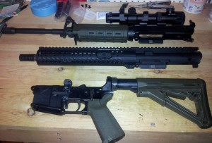
Top: 16″ Stag Model 2 upper
Middle: new 11″ upper
Bottom: Stag Model 2 lower
After all the parts are assembled, I cleaned and lubricated the upper, inserted the borrowed bolt carrier group and fitted the new upper to my Stag lower.
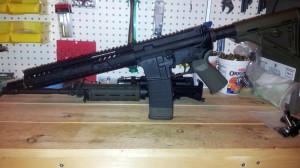
11.5″ upper mated to Stag Lower
After attaching the the new Upper Receiver Group to my Stag Lower Receiver Group I functioned checked the rifle , which is of course unloaded.
1 – SAFE
- Pull the charging handle to the rear and release
- Place the selector on SAFE
- Pull the trigger, and the hammer should not fall
2 – SEMI
- Place the selector on SEMI
- Pull the trigger and hold to the rear. The hammer should fall.
- Continue to hold the trigger to the rear, pull the charging handle to the rear, and release it, Release the trigger with a slow, smooth motion until the trigger is fully forward. The hammer should not fall.
- Pull the trigger. The hammer should fall.
In Part 3 I’ll look at test firing, zeroing the rifle, and then using the rifle at a club practice and the First CQB match of 2013.
Pingback: AR15 Upper Receiver Group Series – Part 1 - Everyday Tacticool
Pingback: AR15 Upper Receiver Group Series – Part 3 - Everyday Tacticool